Advanced Bone Settings
Working with bones in 3ds Max and Wall Worm is fairly simple. There are a few things to understand in terms of how the exporters work and how bones are collected in the export process.
Technically, every object that exports to an SMD is considered a Node, whether it is a Mesh object or a Bone object. Each mesh's pivot exports as a bone and has geometry tied to it. Each bone exports just as a bone node (with no geometry).
Basics
When WWMT exports the SMDs, it automatically sets each node in its export list with the following default logic:
- Each Geometry object is a node with geometry.
- Each Bone object (Bones, CAT bones, Biped Bones, etc) export as nodes with no geometry.
- If any of the Geometry nodes in the export list have a Skin modifier, all bones in the skin modifier are also exported as bones.
- Any node listed in the Bones field of a WWMT Helper modify tab will export as a bone with no mesh.
- If there are hulls, all hull nodes/bones will get added to the root SMD's bone list.
You can assign the export nodes in the main WWMT UI using the Append or Add Sel buttons in the main Model & Basic QC rollout. You can assign either geometry or bones this way. If the order of bones is important, see Bone Order Tips below.
Adding Bones
 If there is geometry you want to explicitly add as a bone and exclude any geometry, you can assign the geometry as a bone instead.
- Select the WWMT Helper in the scene.
- Switch to the Modify Tab in the Command Panel.
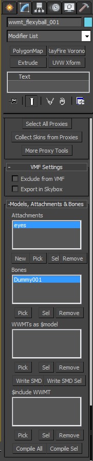
- Scroll down to the Models, Attachments & Bones rollout.
- Click the Pick button and pick a node in the scene to add as a bone.
If you want to set multiple bones at once, use the Assign Button in the Bone Tools floater (requires the WWMT Helper to be open in the WWMT Floater).
Advanced Bone Properties
If you need to set advanced settings for your bones, you can do this by adding the WW Bone Attributes to a Node. Note these settings are for the QC file, not the SMD. They have been designed for Source and will probably not work when Wall Worm is configured for Goldsource.
Add Bone Attributes
The Bones Attributes can be applied via the WW Bone Tools.
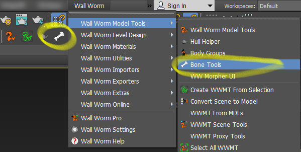
- In the main menus, click Wall Worm > Wall Worm Model Tools > Bone Tools.
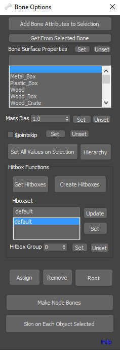
- Select the bone(s) that need modified.
- Click the Add Bone Attributes to Selection button.
Modifying Bones Properties
Once a bone has the bone properties, you can always edit them in the modify tab when the bone is selected. You can see an image of these settings in the far right image to the right.
General Bone Properties
To use any of the general settings, you must check the Use General Bone Properties. This group of options sets parameters including these:
- Add a $definebone to QC
- $bonemerge
- $alwayscollapse
- $root
- $jointsurfaceprop
Collision Model Joints
This section of options relate only to collision models. To use these, click the Use Collision Model Properties checkbox.
- $jointconstrain*
- $rootbone
- $jointskip
- Mass Bias
- Joint Inertia
- $jointcollide
- $jointmerge
- Joint Contents
*Note that $jointconstrain limits are still controlled in the IK tab for the bone.
Jiggle Bone
As of WW 2.4+, Jiggle Bones are no longer automated based on the IK parameters of the bones. Now you must explicitly set jigglebone parameters via this set of options. To use Jigglebones, you must turn on the Use Jiggle Properties chekcbox and then click the Is Jigglebone option. Now set all the parameters available for flexible, rigid and spring jigglebones.
Bone Order Tips
For the most part, the use shouldn't have to worry about the order of bones in the SMD because the hierarchies are automatically calculated from the meshes and bones and the compilers generally use what is needed. There are times, however, that the bone order may matter (for example, if compiling to Goldsource and the root bone in the SMD is important). In this case, it's helpful to understand how Wall Worm orders the bones and how you can control the bone orders.
When Wall Worm first creates the WWMT Helper, the very first object used for setting up the WWMT Helper is internally set as the Root Node (also called the Reference Node). This will always be the first node in the SMD unless another node is set as the first item in the mesh list (or another node is assigned that is a parent of that node via methods listed above).
Changing Bone Order
 There are several methods to change the bone orders of an existing WWMT Helper. Here are the two methods you should use.
Assign a New Root Node with Bone Tools
- Open the WWMT Helper in the WWMT Floater
- Open the Bone tools floater
- Select the node in the scene that you want as the rood bone
- Click the Root button in the Bone Tools floater (image to the right)
Assign a Root Node via Hierarchy
This method presumes that the mesh has a Skin modifier applied and the bone you want to be the root node is already assigned to the Skin modifier. This also assumes that your hierarchy is already set up. If all other children of the hierarchy are already linked, then the mesh will be at the end of the bone list in the SMD. However, if the hierarchy is not set yet, then this mesh will be early in the SMD bone list--so you should do this after all other hierarchy is set if you wish for this mesh node to be at the end of the SMD bone list.
- In the Max main toolbar, click the Select and Link tool
- Select the current mesh for your model
- Click and drag to the new root node (making the mesh a child of the bone)
- Character Models
Articles related to making character models for the Source Game Engine.
- Exporting CAT and Biped Models
- Making Facial Animations
- Advanced Bone Settings
- Related Topics